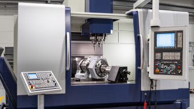
Choosing the best 5-Axis Machines in 2026 is not simply a contest for the newest control. The right choice depends on part geometry, material, production volume, floor space, and the skills available on each shift. A compact trunnion machine may suit aluminum prototypes, while a large table-table platform can better handle tall aerospace components. For steel molds, spindle torque, thermal stability, and sustained cutting performance deserve close attention. Small details matter. Even a capable machine can disappoint when setup, probing, postprocessors, or service response are overlooked.
This guide compares machine types and selection criteria rather than treating one configuration as universally superior. Key checks include axis travel, table load, spindle speed, tool capacity, accuracy claims, and the control’s usability. Look beyond brochure specifications: request a test cut using a representative part, then review the finish, cycle time, and setup steps. Ask how local technicians handle calibration, spare parts, and software updates. That test can reveal more than a polished product sheet. Where published data is limited, comparisons should say so instead of implying certainty. Rankings can also vary with workload; a machine that excels at complex, low-volume parts may not be the best fit for repeated production. Some trade-offs are easy to miss. The sections ahead examine leading options, explain where each may fit, and flag questions buyers should resolve before investing. No shortlist replaces a properly scoped application review, but clear criteria make a shortlist more useful.
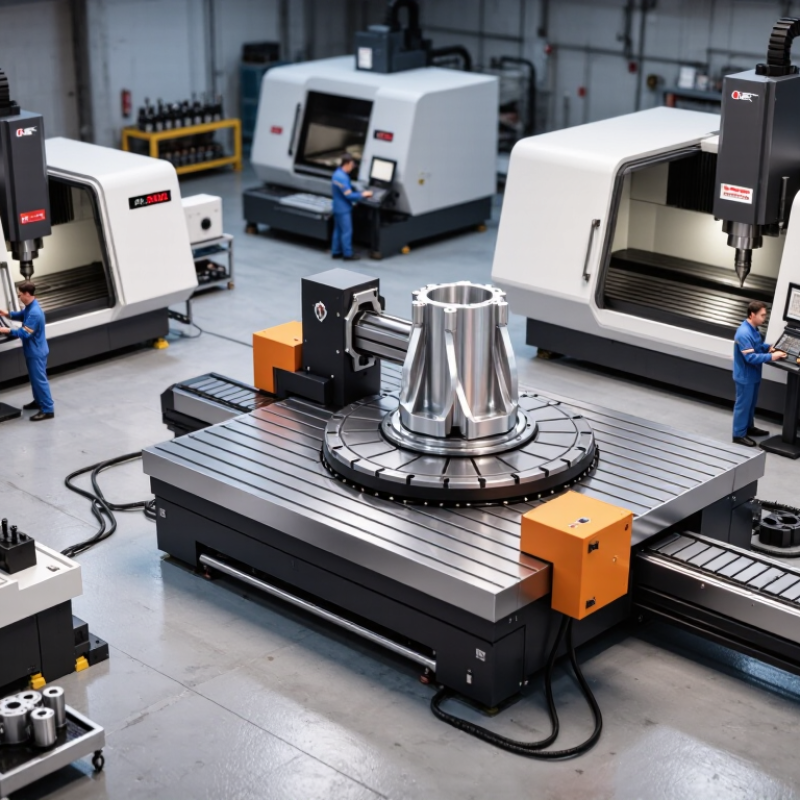
Five-axis CNC machines combine three linear axes—X, Y, and Z—with two rotary axes, commonly described as A, B, or C. The linear axes position the cutting tool; the rotary axes tilt or turn the part or tool. ISO 841 defines standard axis designations for machine tools, helping teams describe movements consistently. Exact layouts vary, so confirm which axes move before planning a setup.
A 3+2 workflow positions the two rotary axes, locks them, then machines using the three linear axes. This can expose several faces of a part without repeated manual repositioning. It is not simultaneous five-axis cutting: the rotary axes stay fixed during each cutting operation. That distinction affects tool access, cycle planning, and whether the approach suits a contoured surface. Grand View Research estimated the global CNC machine market at USD 101.22 billion in 2023; this broad market figure signals investment, not proof that any five-axis process will improve a specific job.
Tip: Check tool clearance with a simulation, then verify the first setup on the machine. A small collision risk can hide near a deep pocket. And simulations depend on accurate fixtures.
| Machine Configuration | Five Axes | Typical Working Envelope | Best-Fit Parts and Materials | Workflow Strength | Key Trade-Off | Best Fit For |
|---|---|---|---|---|---|---|
| Compact trunnion-table machining center | X, Y, and Z linear axes; A and C rotary axes | Typically suited to small parts and workpieces that fit within a compact table and rotary assembly; usable space depends on part height and tilt angle. | Small, complex components in aluminum, steel, titanium, and other machinable materials. | Provides access to multiple sides of a part in one setup; effective for simultaneous five-axis contouring and indexed machining. | The trunnion and fixture reduce usable space, especially for tall parts or large workholding. | Shops making small precision parts, prototypes, and medical or aerospace components. |
| Large-table trunnion or tilting-table machining center | X, Y, and Z linear axes; typically A and C rotary axes | Designed for larger or heavier workpieces than compact trunnion machines; capacity is limited by table load, rotary-axis torque, and part clearance. | Medium-sized housings, plates, impellers, and multi-face components. | Rotates the workpiece to present multiple faces to the cutting tool, often reducing setups and fixture changes. | Rotary motion can restrict access around bulky parts; machine footprint and workholding requirements are substantial. | Production environments that need multi-sided machining of medium-to-large parts. |
| Swivel-head five-axis machining center | X, Y, and Z linear axes; typically B and C rotary axes in the spindle head | Often offers a relatively open table area; practical part size depends on head travel, spindle orientation, and collision clearance. | Large, tall, or heavy components that are difficult to rotate on a table. | Rotary axes move the tool rather than the workpiece, making it useful for machining large parts from several directions. | Head movement and tool orientation require careful collision checking; machine kinematics vary significantly by design. | Manufacturers of large aerospace structures, molds, and heavy components. |
| Five-axis gantry machining center | X, Y, and Z linear axes; two rotary axes commonly located in the head | Can accommodate very large work envelopes; actual capacity depends on gantry span, head design, and machine foundation. | Large molds, composite tools, aircraft structures, and oversized components. | Moves a multi-axis cutting head across a large work area while the part remains stationary. | Requires significant floor space and investment; setup, fixturing, and process planning can be demanding. | Operations where part size makes conventional table-rotating machines impractical. |
| Three-axis machine with a two-axis rotary system (3+2 workflow) | X, Y, and Z linear axes; two rotary axes position the workpiece or tool | Depends on the base machine, rotary unit, and fixture; rotary-axis travel and clearance define accessible orientations. | Parts with features on multiple faces, angled holes, and surfaces that can be machined from fixed orientations. | Indexes the part or tool to a chosen angle, then machines with the three linear axes; can reduce setups without continuous five-axis motion. | Not equivalent to simultaneous five-axis cutting: the rotary axes are generally held stationary during each cutting operation. | Shops adding multi-face capability or machining parts whose toolpaths do not require continuous rotary motion. |
The configurations and working-envelope descriptions are general selection guidance, not specifications for a particular machine. Actual travel, load capacity, accuracy, and suitable part size vary by machine design, tooling, fixture, and cutting process.