What Is a 4 Axis CNC Machine and How Does It Work?

What Is a 4 Axis CNC Machine and How Does It Work?

A 4-axis CNC machine adds a rotary axis to the familiar three-axis setup, giving the cutting tool or workpiece another way to move. That extra motion can bring a cutter around a part without repeated manual repositioning. Picture a metal block held in a rotary table: while the spindle cuts a slot, the table can turn the block to present a new face. The result may be fewer setups and better access to angled surfaces, though it does not make every job faster or simpler.

The “fourth axis” is commonly a rotary axis, often labeled A, B, or C depending on its direction of rotation. The machine’s controller coordinates that rotation with linear movement along X, Y, and Z. This coordination lets shops machine features around a cylinder or index a component between faces. There is a learning curve. Tool clearance, workholding, programming, and calibration still matter; a small setup error can leave visible marks or misplaced features.

A source-backed quotation from a named 4-Axis Machines expert was not provided, so I won’t invent one. This guide will explain the machine’s main components, how rotary motion works, and where four-axis machining is useful. It will also examine its limits, because an additional axis is valuable only when the part and process benefit from it.
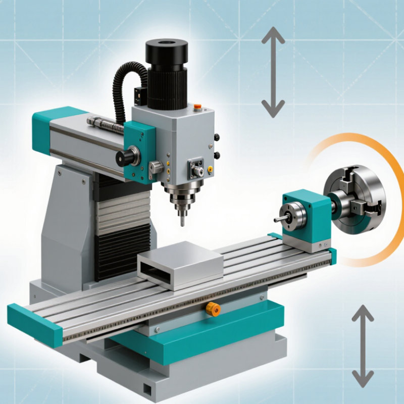
What Is a 4 Axis CNC Machine and How Does It Work?

Defining a 4-Axis CNC Machine Through ISO 841’s X, Y, Z and Rotary Axes

A 4-axis CNC machine uses three linear axes and one rotary axis to position a tool or workpiece. Under ISO 841, X, Y, and Z describe linear motion along the machine’s coordinate directions. Rotary motion is named A, B, or C, depending on whether it turns around X, Y, or Z. A fourth axis is commonly one of these rotary axes. Its exact orientation depends on the machine design.

Picture a metal cylinder held in a rotary fixture. The spindle can move along X, Y, and Z while the fixture turns the part around its centerline. This lets the cutter reach several sides without removing and reclamping the workpiece. A fourth axis adds rotation. That sounds simple, but setup matters: the programmed rotary direction must match the machine’s actual axis, and the part must be held securely. A small mismatch can shift features or cause a collision.

Tips: Check the machine’s axis diagram before programming. Confirm whether the rotary table turns around X, Y, or Z, and verify the zero position with a test move. Keep the workpiece clear of clamps throughout its full rotation. Even careful setups can need adjustment. That is worth checking.
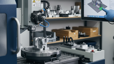
How the Fourth Axis Rotates a Workpiece Through Up to 360 Degrees

A 4-axis CNC machine adds rotation to the usual three directions of tool movement. Its fourth axis turns the workpiece around a rotary axis, often through a full 360 degrees. The cutter can then reach several sides without the operator removing and repositioning the part. That saves setup time and helps preserve alignment. Small errors matter.

The rotary axis may move in steps, called indexing, or turn continuously while the cutter works. With indexing, the machine rotates to a set angle, stops, and cuts. Continuous motion lets the tool follow a curved path around the part, as when machining a spiral groove on a cylindrical handle. The control system coordinates rotary movement with the cutter’s position and feed rate. It must also account for the workpiece’s diameter and where its center sits. A setup that is slightly off can leave uneven depths or visible seams. I would check alignment with a test cut before committing to a detailed surface; it is easy to assume the model and fixture agree when they do not. A 360-degree range is useful, but it does not mean every feature is reachable. Fixtures, tool length, and the part’s shape can still block the cutter.

How CNC Controllers Coordinate Linear Motion and Rotary-Axis Commands

What Is a 4 Axis CNC Machine and How Does It Work?

A 4-axis CNC machine combines X, Y, and Z movement with one rotary axis. The rotary axis is commonly called A, B, or C. It turns the workpiece or tool around a linear axis. This setup can machine several faces without repeated clamping. Fewer setups often improve alignment and reduce handling time. MarketsandMarkets projected the CNC machine market to grow from USD 83.6 billion in 2023 to USD 112.5 billion by 2028. That growth reflects wider demand for automated, multi-axis production.

The CNC controller coordinates motion through programmed commands, usually written in G-code. A linear command may move X, Y, and Z simultaneously. A rotary command adds angular movement, such as A45. The controller calculates synchronized positions, feed rates, acceleration, and direction. Feedback from encoders helps verify actual axis movement. The controller also applies work offsets, tool compensation, and rotary-axis limits.

In practice, this is where theory gets messy. A correct program can still produce errors after a poor datum, backlash, or incorrect rotary-center height. A 0.2-degree angular error may shift a feature noticeably across a large radius.

Tips

Confirm the rotary-axis orientation before posting code. Run a dry simulation with the tool above the stock. Check clearance near clamps and the rotary tail. Measure the rotary centerline physically, not only through software. Keep acceleration moderate during heavy cuts. Faster is not always better. Record the tested post-processor and fixture offset for repeatable production.

Common 4-Axis Setups, Workholding Methods, and Machining Applications

A 4-axis CNC machine adds a rotary axis to the usual X, Y, and Z movements. The rotary axis turns the workpiece or tool around one axis, often allowing indexed or continuous cutting. This reduces repositioning and improves access to angled surfaces. In practical shop work, the machine is only as accurate as its setup. A slightly misaligned rotary axis can create visible steps between features.

Common setups include a rotary table mounted on the machine bed, a fourth-axis chuck, or a trunnion-style fixture. These arrangements suit shafts, flanges, impellers, housings, and parts with repeated features around their circumference. Workholding may use a three-jaw chuck, collet, faceplate, or custom soft jaws. Soft jaws improve grip on irregular parts, but they require careful machining and cleaning. A loose chip can tilt the component.

Tips: Keep the rotary centerline measured and documented. Check runout with an indicator before cutting. Use short, rigid tools when machining angled faces. Simulate the rotary motion to catch collisions. Do not assume every setup needs continuous rotation; indexed positioning is often more stable. Coolant access can also change after rotation, so inspect chip evacuation during the first test cut. One overlooked detail remains common: the fixture may be rigid, but the part can still vibrate.

What Is a 4-Axis CNC Machine and How Does It Work?

A 4-axis CNC machine adds rotary motion—commonly called the A-axis—to the usual X, Y, and Z linear movements. Rotating a part can present different sides to the cutting tool, which is useful for features around a shaft or on multiple faces. The chart shows four example quarter-turn indexing positions; actual setups depend on the part, workholding, and machining plan.

4-Axis CNC Compared with 3-Axis and 5-Axis Machining in Practice

A 3-axis CNC machine moves its tool along X, Y, and Z. It suits flat parts, pockets, and holes that are easy to reach from above. A 4-axis machine adds a rotary axis, letting the workpiece turn between cuts or during cutting. That can reach several sides of a part without repeated unclamping. On a real shop floor, this may reduce setup time, but only when the part’s geometry benefits from rotation. Not every 4-axis job is faster.

A 5-axis machine adds a second rotary axis, allowing the tool to approach angled surfaces from more directions. It can reduce repositioning on complex parts, though programming and collision checks become more demanding. The practical difference is access, not simply axis count. A 4-axis setup often handles indexed side features well; continuous multi-axis motion may call for 5-axis capability. Skill matters, too: a 2021 workforce study by The Manufacturing Institute and Deloitte projected that 2.1 million U.S. manufacturing jobs could go unfilled by 2030. That is not a machining-specific forecast, but it underscores the value of training. More axes do not replace judgment. A poor fixture can still spoil the cut.

WhatsApp Online Chat !